Using Parametric Features in Dynamic Block
Using Parametric Features in Dynamic Block
December 4, 2009 by
Parametric feature is very useful if you have similar object with slightly different geometry or size. In manufacturing, if you have nuts and bolts that looks the same, but have different sizes, parametric features is perfect for this purpose. This kind of remind us about dynamic block, isn’t it? Dynamic block has the same purpose, but has limitation. I can’t figure yet how we can use it in AEC industry, except for reusable contents.
So this time, we are going to create a column with dynamic block. This is similar with the column we created in dynamic block tutorial. But we are not using the parameter and action. We are going to use geometric and dimension constraint. We will see how we can get different dynamic block behavior.
For a start, let’s create two rectangles like this.
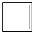
I made a 200x200mm rectangle and offset it 20mm to outside. The 200x200mm is the column, and 20mm is the column finishing layer. Make it as a block, and use the center of the rectangle as insert point. Same like we did before.

As usual, to add ‘dynamic’ behavior to the block, we need to open it in block editor. Let’s forget the block authoring palette for a while. We will focus on the contextual tab: block editor.

Let’s activate the dimensional constraint. use linear dimension, and snap to the rectangle end points. Change the constraint name immediately to h and w like below.
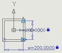
Now we will tell AutoCAD that we want the finish thickness is 20mm. Let’s add one more constraint, name it finish.
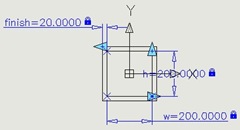
Here is the deal. We have four rectangular sides that need to define the offset distance. Add them all and when AutoCAD ask you for the value, type ‘=finish’. It means we are going to use the same value as the previous constraint.
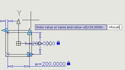
And when AutoCAD ask you the number of grips, enter 0. We don’t need it since we refer to ‘finish’ constraint. Here is the finished dimension constraint placement.
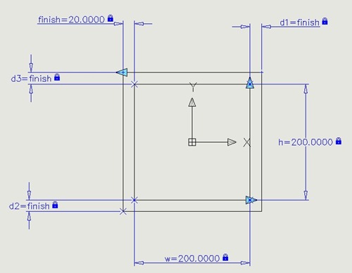
We haven’t finished yet. But let’s test it before we continue. Click parameter manager button on your ribbon.
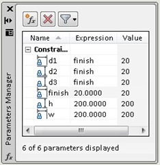
As you can see, the result can be unpredictable! Why? We haven’t tell AutoCAD the objects relations to each other. We need to add geometric constraint.
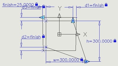
Undo until you see the rectangle back. We will add geometric constraint to these rectangle. Instead of adding them one by one, let’s activate Auto Constraint. Press S then [enter] to change the settings. Deactivate all, except perpendicular. We want or rectangle sides to be perpendicular to each other.
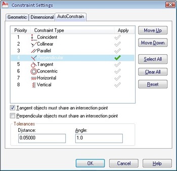
Click OK then select them all. Add one horizontal constraint to any horizontal edges. You can left the whole constraint on actually. Not just the perpendicular. I just want you to know the option exist :)
Try to change the parameters again. We still have a problem: the insertion point is shifted.
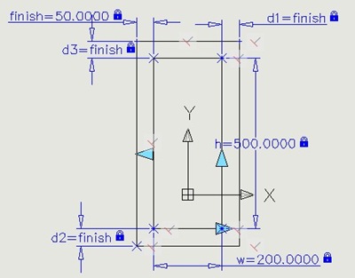
The last thing, we need to define a fixed point as the center of the column.
Let’s create a point at #0,0. You can activate point by typing POINT then [enter]. Then type #0,0 [enter]. If you can’t see the point, type DDPTYPE [enter] to change the point appearance.
Lock it at its position using fix constraint.

Now add dimensions from the point to the rectangle edges. Use h/2 and w/2 as the value. This will make sure our column center won’t shifted.
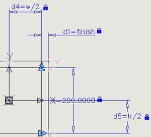
Let’s try again. Does it work?
We will explore this column again next time.


Komentar
Posting Komentar